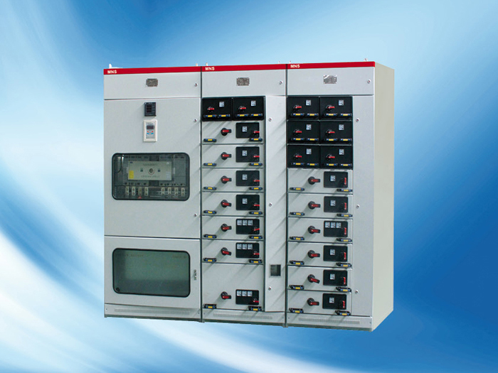
HLMNS low voltage draw out type switch cabinet
- Brand:
- Type:

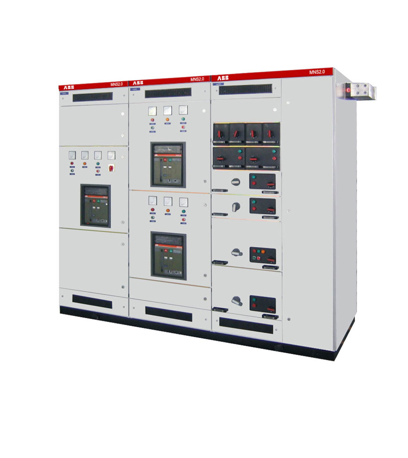

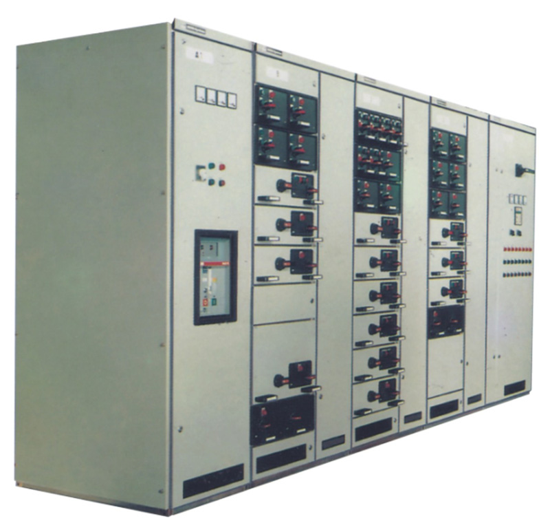

Device applicable to power plants, substations, petrochemical enterprises, factories, mines and other enterprises, high buildings and other low voltage distribution system power distribution, motor control center, electric energy converting to distribution and control of compensation capacitors. In the big single machine capacity of the generator, large-scale petrochemical industry low voltage power control center and motor control center, power use occasions can meet with the special needs of computer interface. This device complies with GB7251.1-2005, low pressure JB/T9661-1999 out of type switchgear, iec439 standards.
1 normal operating conditions
1 ambient air temperature is not higher than +40, not less than -5 degrees Celsius, the average temperature within 24 hours is not higher than +35;
2 altitude is not more than 2000m;
3 ambient air relative temperature at the maximum temperature of +40 degrees Celsius is less than 50%, at a lower temperature allows a larger relative temperature;
4 switch cabinet installed with a vertical tilt of not more than 5 degrees.
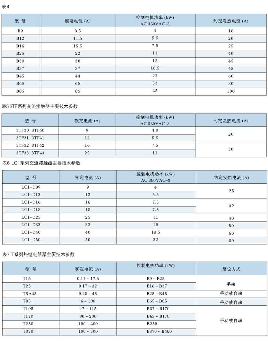
2 main technical parameters
Rated insulation voltage AC 1000V, 660V
Rated operating voltage main circuit AC 660V, 380V
Auxiliary circuit AC 380V, 220V
Rated frequency 50Hz, 60Hz
Rated current 4000A
Rated current of vertical busbar 1000A
Rated short-time withstand current (1s) 50kA ~ 80kA
Rated peak withstand current 105kA ~ 176kA
Vertical busbar rated short-time withstand current (1s) 50kA
Rated peak withstand current of vertical busbar 105kA
Shell protection class IP40
Special use of the environment up to IP50
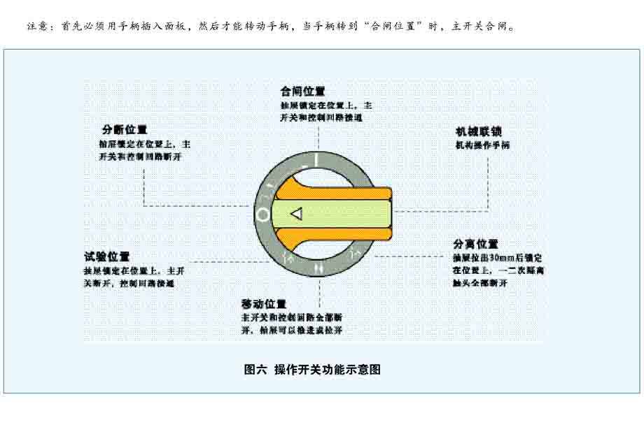
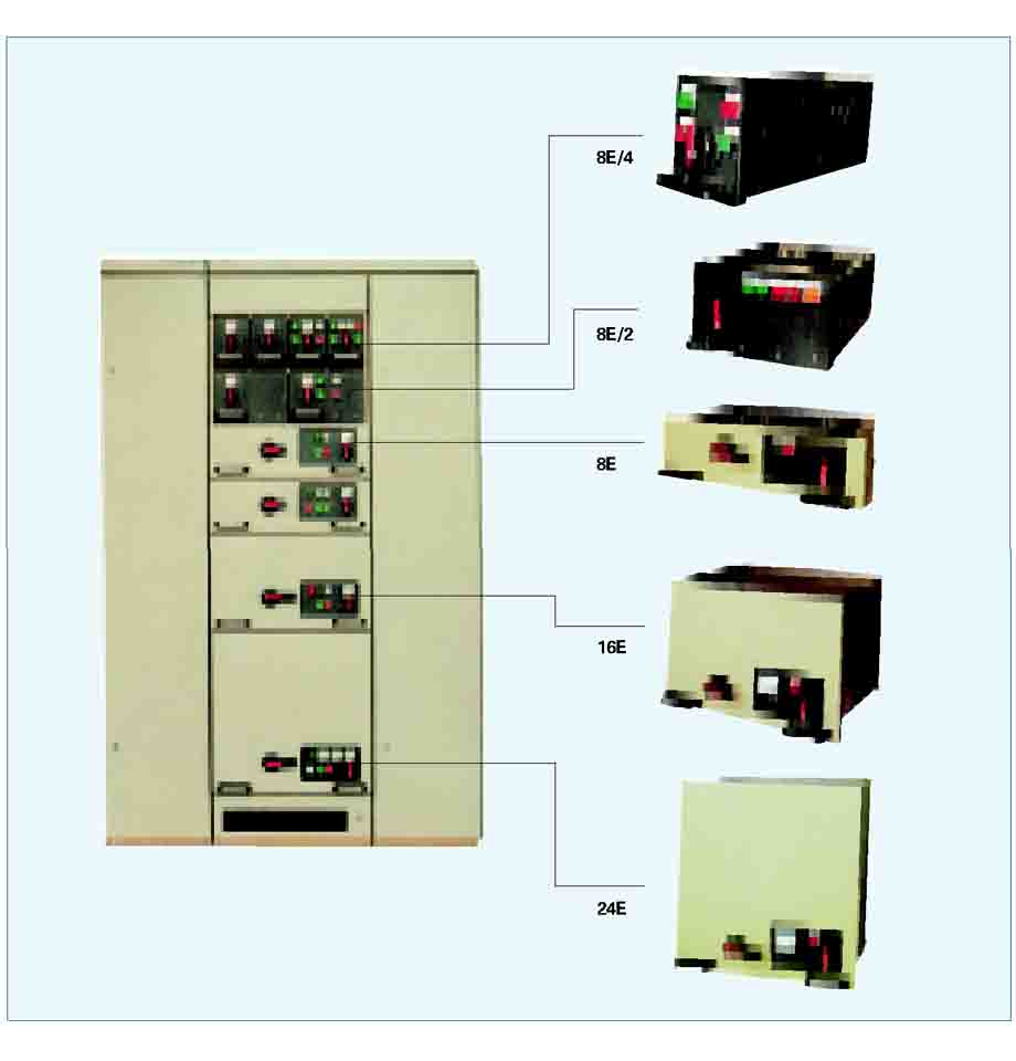
3 Drawer operation and mechanical interlock
And the formation of "separating out of the implementation should be: 8E/4,8E/2 drawer unit operation the operation is based on the panel of the drawer handle operation, as shown in Figure 6. Only when the handle of the white arrow" mobile location (arrows NaBH), the drawer can be pulled out or inserted in any other position, the drawer is locked, so impossible to the drawer out or insert operations. At this time is not a hard pull or dragged so as not to damage the mechanical interlocking mechanism, chest of drawers and the connection position of 30mm (then in the hands of a workpiece slight tremors) when the operating handle to the counter clockwise turn 45 degrees, the drawer is locked in position "() at a time and secondary isolation plug has been off the grid interval.
And does not match the requirements in introducing the drawer is inserted after the handle clockwise direction of rotation, was the first to reach the "test" (). At the same time, the agency will be the external power supply control circuit, the user through the panel on security appliances (if any) of the circuit trial operation, to confirm whether meet the requirements, the main switch is in the off state, so a loop without electricity, even if the operation results and will not damage to the device and continue clockwise direction of rotation to the handle in a horizontal position, namely "off position" (o). At this time a secondary circuit in electric state along the clockwise direction to rotate 90 degrees, the handle to the closing position "(I), as shown in Figure 6.
8e, 16e and 24E drawer operation: the slightly different in 8E/4 and 8e / 2: drawer unit operation, performed by turns the operation of a two handle. Small handle and 8E/4,8E/2 drawer of the operating handle is the same shape, mechanical interlocking, located at the bottom right of the drawer panel. It has a total of four positions: the "location" (arrows RS1) "separation" (), test position "() and" connection position "(), as shown in Figure 7, figure of eight.
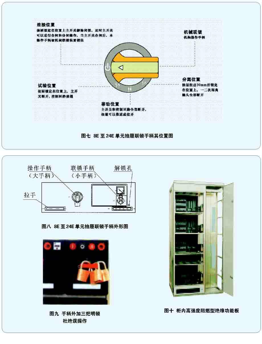
The operation and the position of the definition and 8E/4,8E/2 unit operation in the small handle handle is basically the same, only there is no "off position" instead of "connection position (). Only when the handle is in this position, it can operate the main switch operation handle (a). A" broken Arrow Cross location "to the left, the first and two circuit is in a state of no power, large handle clockwise to the arrow upward when the closing position, the main switch is closed. A small handle and a large handle operation with mechanical interlock strictly, not free operation, but can not pull the dead lever. Note: ridge only a small handle in the" connection position ", to handle large closing operation; at the same time only in the" handle position off ", less than the handle can rotate. Although sometimes large handle is also in position off" but positioning, it will make a small handle not Can rotate or rotation is not in place, this time must not be hard to pull, should be a little bit of a large rotation of the handle so that it can be accurate in place.
When the switch is in a drawer and locked position, can add three to the external Suosuo check, to prevent any possibility of misoperation.
When accidental short-circuit fault occurred in the circuit, circuit breakers and other main switch occurs contact welding so that it is difficult to jump not, want to the fault drawer the implementation of maintenance, appropriate tools available, such as a screwdriver) insert unlocking hole on the panel will the internal locking downward pressure can open the door, open the buckle piece is rotated to a vertical position can be, rotation handle to release interlocking, can make the drawer out of the cabinet and the implementation of the maintenance.
4 busbar and protection grounding system
The level of bus installed in the cabinet level interior line, for allocation to the two groups of buses. When the level of bus is a bus group, according to need to install it in busbar room above or below. When the bus level for the two sets of bus, general in the upper part and the lower part of the installation of a group. Two groups of bus can parse operation, but also can be operated in parallel.
Vertical busbar installation in high strength and flame retardant insulation board, front cover, the protection level of the room reach IP20. Function in both as a vertical bus insulating support, and can separate vertical and horizontal bus bus. Vertical busbar adopts L-shaped profiled bar. It can not only through the rated working current, and can withstand the larger electric power.
Neutral bus (n) and protective earthing busbar (PE) parallel installation in the functional unit compartment of the lower or vertical installation in the cable compartment, the N line and PE line between such as insulator apart, is n line and PE line were used. PE+N (three-phase five wire) line; between the two such as conductor short circuit, i.e. pen line (three-phase four wire).
5 auxiliary circuit cable groove
An auxiliary circuit cable groove is arranged at the top of the functional unit compartment, and the connecting wire of the cabinet can be arranged in the groove.
4 transportation and installation
1 transportation of products
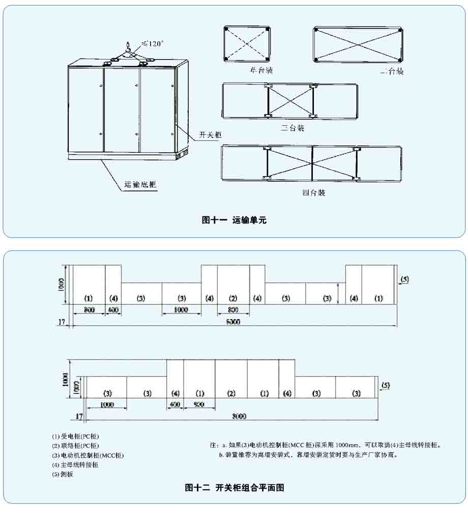
Transport unit: products are divided into four types of transport units: a single pack, two sets, three sets and four sets. But the total length of not more than 3m, see Figure eleven.
Products of lifting (loaded): products in the hoisting and installation in the process of lifting must be as in Figure 11 dotted line hanging wire rope, wire rope angle not greater than 120 degrees, lifting should be smooth, to avoid strong vibration, shaking and impact.
2 product installation
A combination of switches, see Figure twelve.
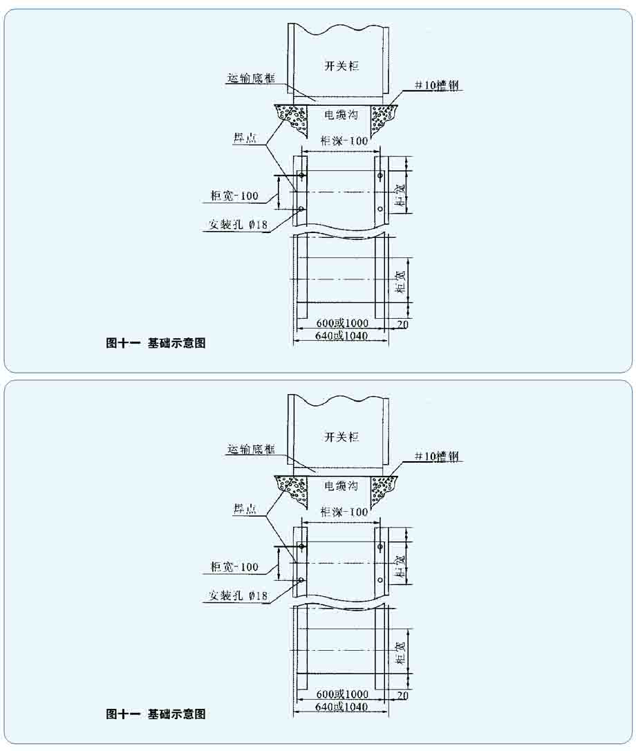
Foundation treatment: the width of the cable channel selected by the user's own, channels 10# according to figure 11 pre buried and flush with the ground. If the transport at the bottom of the cabinet and the foundation channel steel bolt connection, the foundation channel steel mounting hole size as shown in Figure 11 planform.
Installation: switch cabinet in place. To identify the location, as Figure 11 shows welding, welding section cabinet and weld length is determined by the user, product installation and distribution room of the relative position of reference Figure 12. The sling is installed is determined by the user, supplied by the manufacturer of the principle is: when the bus bar bridge length greater than 3 meters should consider installing sling. However, when the bus bar bridge current is greater than or equal to 2500A, its length for 2.5 meters should be the installation of hangers.
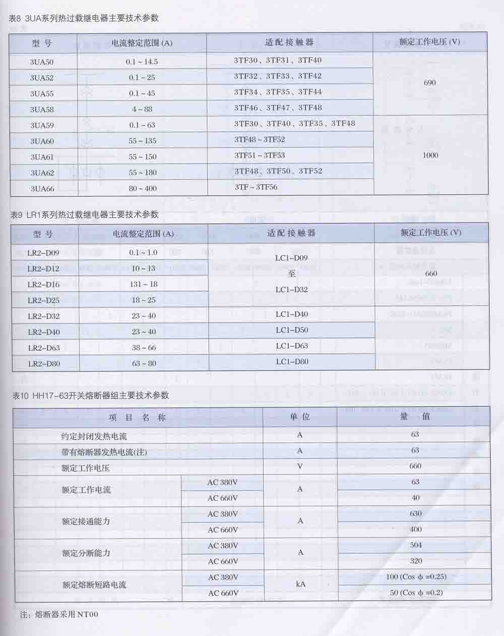
5 technical parameters
6 ordering instructions
10.1 primary circuit scheme or single line system diagram;
Two 10.2 circuit principle or wiring diagram;
10.3 products of the first and two equipment list;
10.4 arrangement and distribution room layout;
10.5 product surface coating and color.