
HLGH-Z PV junction box
- Brand:
- Type:

Product introduction
1 instructions for use
Thank you to select the company bus products, in order to ensure that you successfully use the product, please read this manual carefully before installing, and according to the way provided in the manual to operate.
All installation of the junction box, wiring and other operations should be carried out by electrical professionals, and comply with the relevant content in this note, otherwise it may cause electric shock damage or affect the performance of the junction box.
After receiving the product, please check the packing list:
Table 1 bus standard configuration
Name unit quantity
Bus station 1
Factory inspection report 1
Certificate of qualification 1
The door key to the 1
2 performance indicators
2.1 Product Overview
6~16 road junction box contains a variety of specifications, including intelligent and non intelligent, anti type and non - type and other specifications. By the box, SSU (Smart Solar Unit) monitoring component, circuit breaker, fuse, arrester, input and output connector components, maximum allowable input circuit number 16, each input rated current is 10A, rated voltage up to 1000V. junction box adopts many new techniques, can achieve free inspection, remote monitoring, remote breaking etc. junction box designed to free out of the box, all external wiring through the plug connection, greatly saves the construction work all parts are made of French Schneider, French Citel, Copper Bussmann, Phoenix and other international well-known brands, to ensure the long-term stability of junction box in a variety of harsh environment, reduce the routine maintenance work, at the same time also reduced due to Daily maintenance, unpacking and work on the product damage.
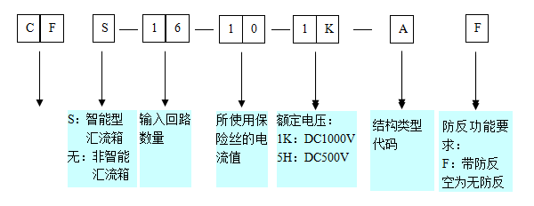
2.2 model description
Model description of DC lightning protection junction box:
2.3 technical performance
Solar energy intelligent junction box mainly has the following properties:
At the same time, the maximum access to 12 inputs, each current maximum is 10A, voltage up to 1000V;
It is equipped with full protection of the connection of the photovoltaic special lightning protection device, electrode with lightning protection function;
Schneider adopts special photovoltaic DC circuit breaker and Yinrong PV special fuse, provide two level overcurrent protection;
To support RS485 communication based on the communication between PC and convenient;
You have a loop current detection and voltage detection function, can real-time display the circuit input current and bus voltage;
It is safe and reliable connection, make installation and maintenance more convenient, simple, long service life;
Between box and door used to seal the dispensing process, ensure the protection level of box.
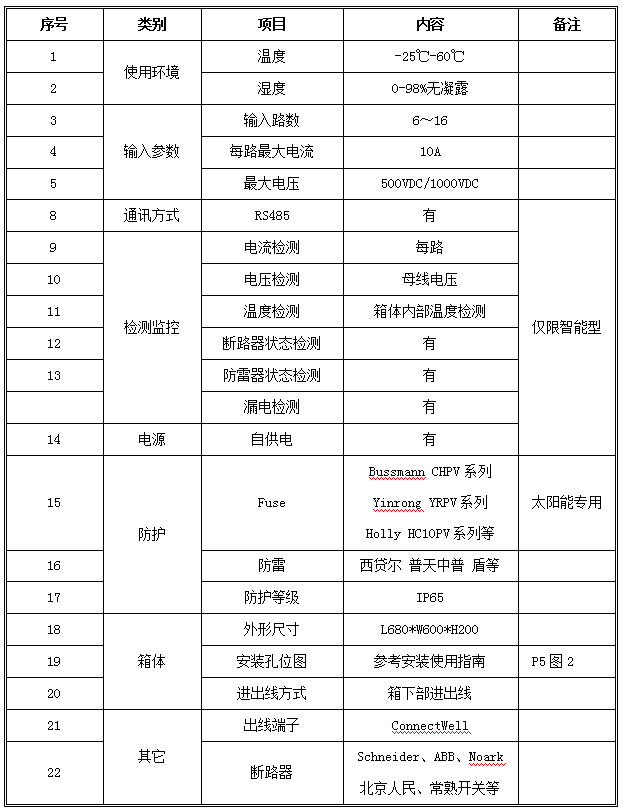
2.4 technical parameters
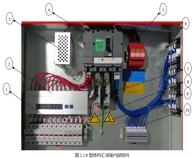
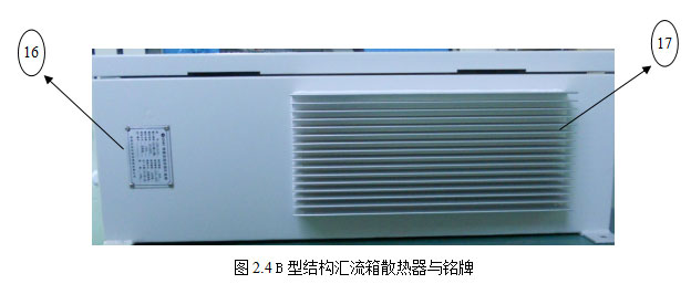
2.5 B structure bus structure and description
As described in 2.2 content, junction box structure divided into two kinds of type A and type B. A type structure for the non symmetric structure, B type structure is a symmetrical structure. The B type structure of the junction box of the internal structure and function as shown in Figure 2.4 and table 2.2 The.
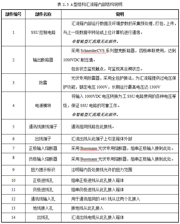
2.6 A structure bus structure and description
The internal structure and functions of the A type structure junction box are shown in the following figure 2.5-2.6 and Table 2.3.
2.7 SSU operation and display functions
The intelligent monitoring unit SSU has a 8 bit LED display and two buttons K1, K2, which is used to display the running data of the bus in the bus:
1, no key action:
LED display: according to the bus voltage, bus current, temperature, 0~16 circuit current of the order state shows that the time interval is about 2S
2, K1 press:
Function: switch to the next state
Description: displays the current state of the next
3, K2 press:
Function: no
Description: display ERRORS, the normal order according to K2 no effect
4, the combination of keys, K2, K1 at the same time press:
Condition: need to disconnect the communication line
Function: view from the machine address, and set the address
Description: while pressing the LED flashes 3 times, display the machine address, with a decimal point for the current variable position, K1 press standard plus 1, K2 variable position to the left moving a, set the address, while pressing the K1, K2, the LED flashes three times back to normal, the address setup is complete, restart after effect.
3 installation guide
Warning!
Please before wiring and installation of the box to determine all that is needed for the operation of wire and cable are in the power of state, or it may be caused by lightning damage. During the installation and connection with the battery plate, in particular, to pay attention to first determine the panels without any current or voltage output.
3.1 to use the installation tools and accessories
Table 3.1 requires the use of installation tools and accessories
Specification for tools and accessories
Internal six angle screwdriver M6
Wrench 8 inch 200mm
A screwdriver 100mm
Cross screwdriver 100mm
Screw 4, M6
3.2 mechanical installation
Bus unified use of the same size and installation of the same size. The size of 600mm x 600 x 210mm (W x x x x x x x x x x x x x x x x x x x x x x x x x x x x x x x x x x x x x x x x x x x x x x x x
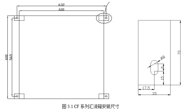
Flow box with wall mounted, can be installed on the wall, bracket or other support.
When the wall is installed or installed in the plane material thickness, can be in accordance with the size of the installation plane hole drilling, and then use the expansion screw or other ways to install the four attachment holes on the application of M6 screw tightening.
If installed on the bracket or where the plane material is thinner, you can get through the hole, and then use the bolt for a fixed installation.
3.3 electrical connection
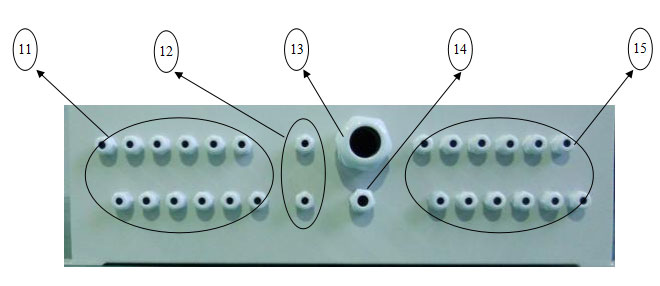
Junction box of electrical wiring can be classified as string input wiring, output bus wiring, wire and network communication line four parts. All electrical wiring is located in the box at the bottom of the waterproof connector insertion to the inside of the box are connected, connection lock tight waterproof connector from the.
Line specification for 3.3.1
Before conducting the junction of the junction box, make sure to use the correct specification of the wire.
1 wire current carrying capacity is correct.
Control the junction box on the right side of the lower part of the wall plate, the input and output parameters of the search to the junction box. The rated input current 10A of the junction box, each input, please use not less than AWG13 specifications (or national standard 2.5mm) wire to connect; for the rated current for 20a of the junction box, each input to the use of not less than specifications AWG10 (or GB 6mm2) of wire. Similarly, output circuit of the wire to the rated current of the reference junction box input channels and each channel. Specific line specifications can refer to the relevant electrical standards.
2 the diameter of the wire is suitable.
Waterproof connector locking range is limited, we must use the appropriate size of the square wire can ensure the reliable locking will not be waterproof. Our company junction box products in the design fully consider the connection, according to the input output current specifications general wire diameter size is calculated and choosing appropriate range lock tight jacket.CF series junction box used waterproof connector locking range is as follows:

Note: please be sure to confirm that the outer diameter of the junction box is in the locking range of the above table. Using the wire outside the above range will cause the cable to be unable to pass through the waterproof connector or the waterproof connector can not be locked tightly.
3 selection of communication lines.
485 communication line, be sure to choose standard STP, recommended line diameter not less than 1.0mm -.
3.3.2 group input connection
Recommend the use of crimping terminal, will be peeling wire head pressure connected access fuse or terminals, to ensure the connection reliability.
The sequence of the sequence of the group should be noticed, from left to right in order to loop 1, loop 2...... Loop 16, and positive and negative to the corresponding, or may result in the display of the group is not allowed to monitor the current series of positive wire connection as shown in Figure 3.2 below.
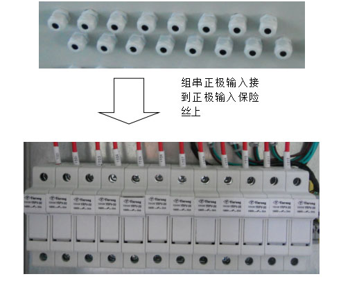
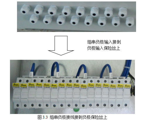
The 3.2 group of positive electrode wire is connected to the positive electrode.
A series of negative terminals are connected to the negative input fuse or the negative input terminal.
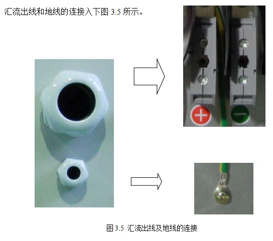
Connection of 3.3.3 bus line and ground wire
The output of the junction box is connected to the output terminal or the output circuit breaker.
3.3.4 networking communication line connection
The wiring of network communication line is shown in Figure 7
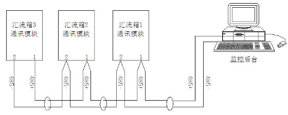
Fig. 3.6485 schematic diagram of network communication line
Be careful:
1.485 the positive and negative polarity of the communication line must be correct, otherwise it will lead to unable to communicate.
Be sure to use the standard 2.485 line shielded twisted pair wire diameter not less than 1mm. And with the strong electric field - Part separate the line.
3.485 communication theoretical distance can reach 1000 meters. But based on the actual conditions of the site restrictions, it is recommended that the communication distance should not exceed 100 meters.

3.4 product use
1 before the official use of the bus, please be sure to check all the installation and wiring work is over, the junction box is firmly and reliably, the relevant electrical connection parts without metal impurities, etc., no personnel to continue the installation operation and so on.
2 power supply, the test input and output is normal, you can officially put into long-term use.
3.5 transportation, loading and unloading process matters needing attention
You should avoid violent vibration and impact in the process of transportation, product packaging and placement to firmly, so as not to slide.
To loading and unloading process to avoid collision, falling off and rewind, handling and use tools must be standardized, professional.
To avoid in the harsh environment (high temperature thunderstorm, etc.) for transport, loading and unloading.
4 quality assurance
The product shelf life of the bus is 18 months. During the warranty period, the company will repair or replace the product for free.
Note: the following conditions are not within the scope of the company's quality assurance:
To machine parts have been beyond the free warranty period
The damage caused by improper transportation, transportation or handling process.
Or because of the earthquake, fire, flood and other no fault and damage caused by force majeure.
It is not the correct installation, modification or use
The machine malfunction or damage caused to run beyond the manual very harsh environments or illegal operations
Some non service personnel to install, repair, machine failure or damage caused by the demolition or change
Due to machine failure or damage, resulting in the use of non-standard or non original parts or software
It product serial number label has altered, replace, tear phenomenon
You are not a serial number or three packets on the certificate number and product model number or product.
From the above situation caused by product failure, customer requirements for maintenance services, the company allows, can provide paid maintenance services, if the product size and parameters are changed, the company's latest information is subject to without further notice.
5 common fault handling
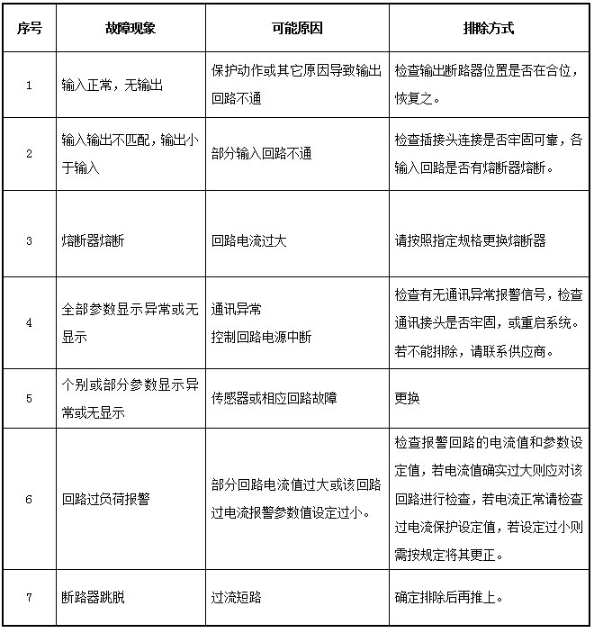
If you are still unable to solve the problem through the above problem, please record the failure in detail, and contact us.
6 product implementation standards
The manufacture, test and acceptance of the solar energy intelligent junction box meet the following standards:
* SJT 11127-1997 photovoltaic (PV) power system overvoltage protection - Guide
GB/T18479-2001, terrestrial photovoltaic (PV) power system overview and guidelines
I GB/T 191 packing and the sign
Basic environmental testing procedures for testing A GB/T 2423.1-2001 electrical and electronic products: Test Method for low temperature
Basic environmental testing procedures for testing B GB/T 2423.2-2001 high temperature test method for electric and electronic products.
GB-T / 2423.3-2006 environmental testing for electric and electronic products part second: Test Cab damp heat method
GBT, general specification for 3873-1983 communications equipment products packaging
GB / 4208-1993 protection grade (IP code)
GB 4943-2001, safety of information technology equipment
I GB-T 3859.2-1993 semiconductor converter application guide
Compatibility testing and measurement techniques, GBT 17626.5-2008 electromagnetic surge (impact) immunity test
GB, 7251.1-2005 low voltage switchgear and control equipment