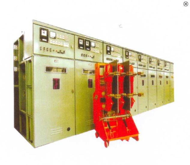
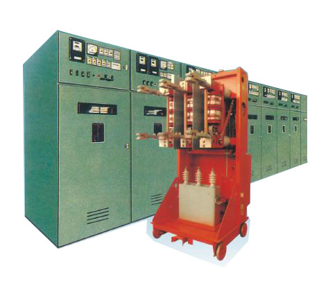
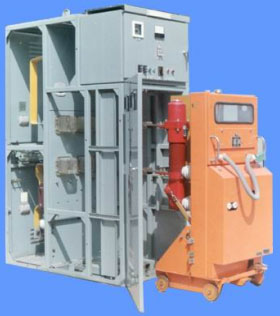
JYN2-12kV metal closed interval type movable switch cabinet
- Brand:
- Type:


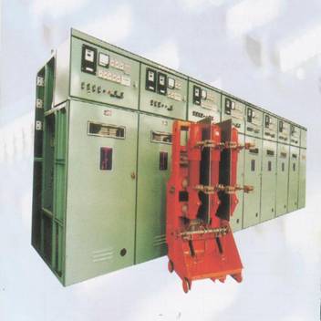
JYN2-10KV switch cabinet for 3.6-12kV single bus system for receiving and indoor type metal seal distribution of power switch devices.
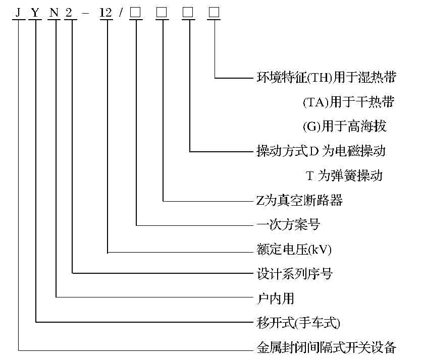
Model meaning
Normal use of environmental conditions
1 ambient temperature: upper limit of +40, lower -5
2 altitude is not more than 1000m;
3 month average relative humidity is not more than 90%, the average relative humidity is not more than 95%;
4 places where there is no fire, explosion hazards, serious contamination, chemical corrosion and violent vibration;
5 earthquake intensity is not more than 8 degrees.
3 installation, adjustment and use
Outline and installation dimensions
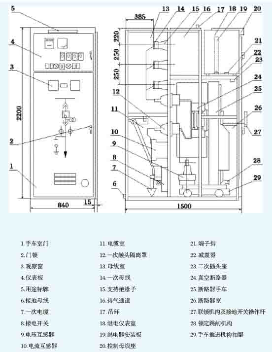
1 outline drawing (see Figure 1)
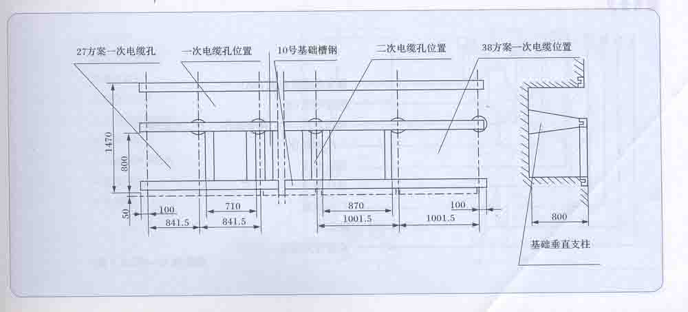
2 switch cabinet base mounting holes (see Figure 8)
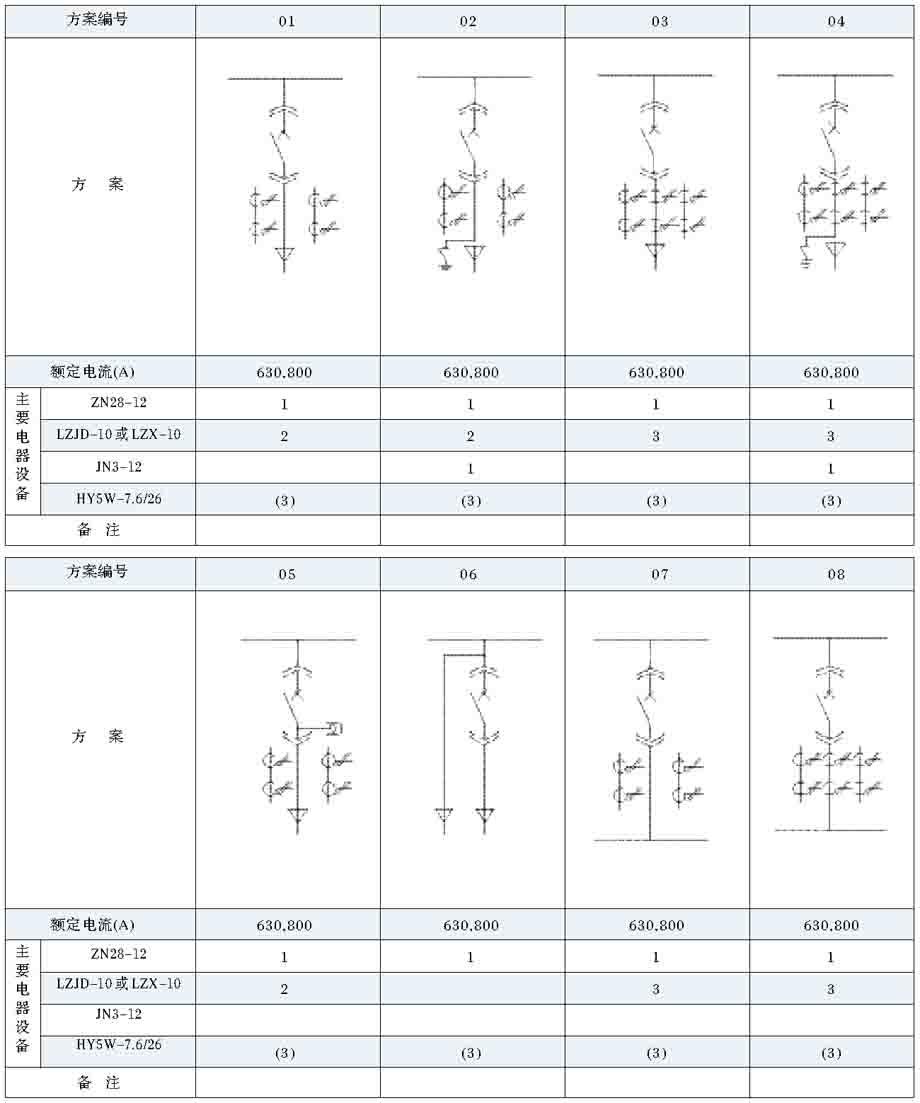
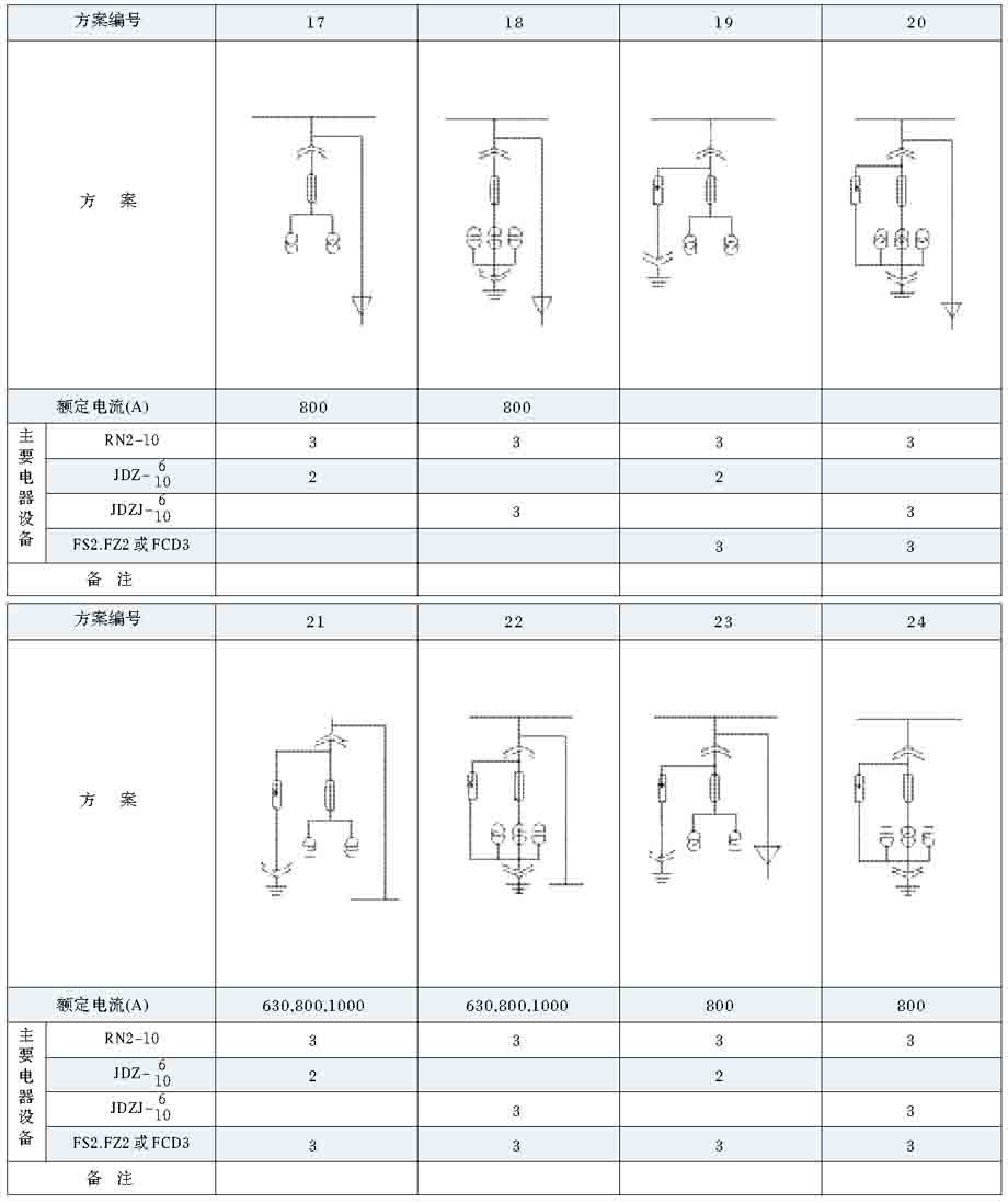
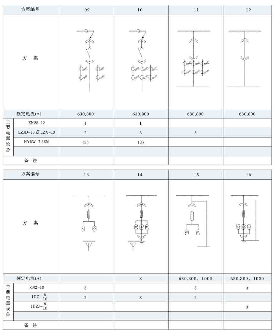
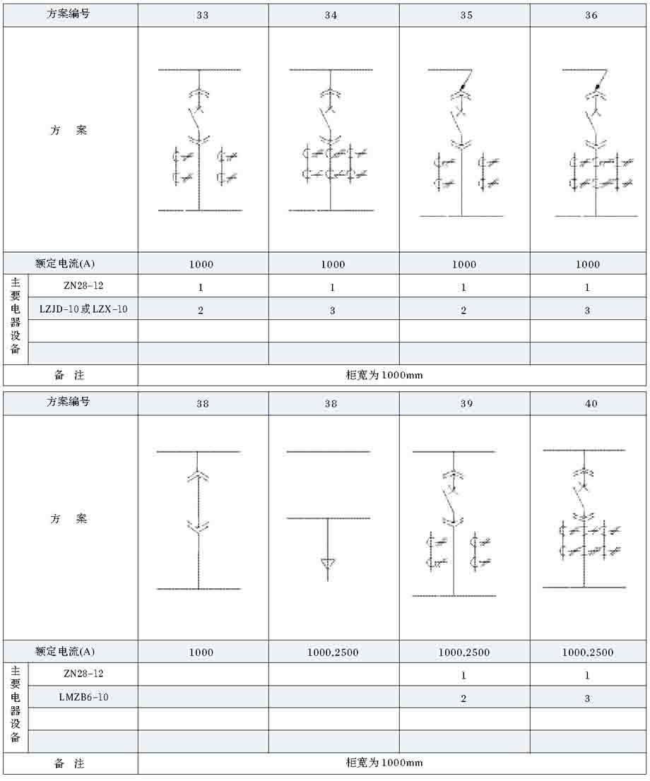
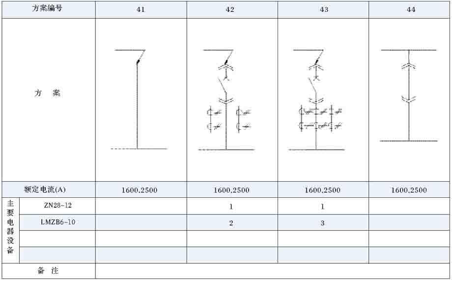
Switch cabinet of a program (see Table 2)
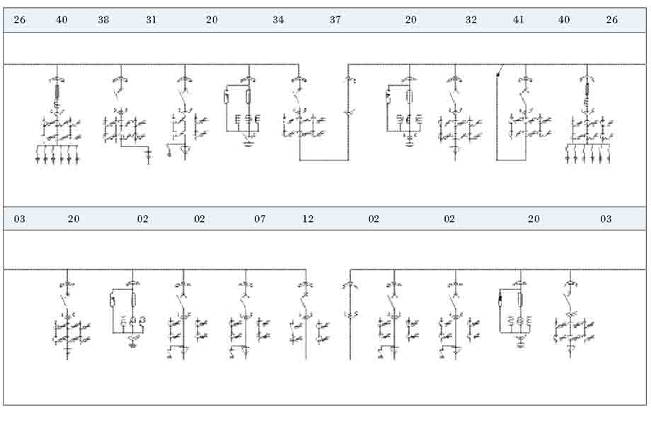
Example of a combination of programs (see Table 3)
Installation, adjustment and use
1 installation
1.1 in operation caused by up and down moving load is less than 7850N.
1.2 basic construction requirements
Switch cabinet installation reference Figure 9, basic flatness requirements for: every 1m allows the error is not greater than 1mm.
1.3 grounding
The earthing busbar of the cabinet should be grounded reliably.
2 adjustment and use
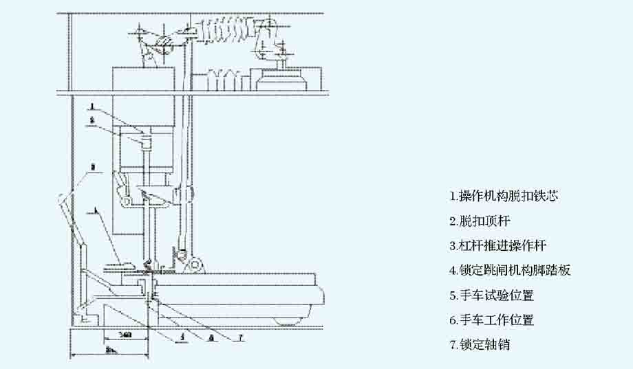
When the switch cabinet installation, cleaning equipment in the power distribution room, and switch cabinet, to ensure the cleanliness of the switch cabinet, no other debris, then adjust and test work. In military vehicles in the test position, locking pin shaft should be correctly inserted into the positioning hole of the test, the test position switch SP1 should be reliable action and connected to the second plug seat, the circuit breaker and the grounding switch can switch.
Pedal locking tripping mechanism, hand car moves between the test position and a working position, the circuit breaker operating mechanism in a state of tripping, test position switch, Sp1 and working position switch SP2 action to ensure circuit breaker in the switch state, grounding switch can not be closed.
Hand car arrived at work position, then the following conditions should meet:
A. lock shaft should be correctly inserted into the positioning hole of the work, the work position switches should be reliable action, the circuit breaker should be capable of closing.
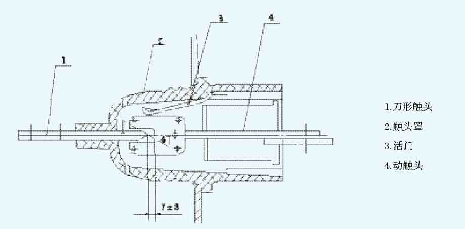
B. an isolated contact contact, the contact depth of 7 + 3mm, the level of asymmetry of 4mm;
C. two contact should be locked by the body, can not be pulled out;
D. earth contact should ensure that the hand car and the shell of the grounding circuit is reliable, the contact resistance should be not more than 1000 mu;
The measurement data of the contact resistance of the E. primary isolation contact group shall be less than that specified in the following table:
After the installation and adjustment should be one and two times of the cable hole blocked to prevent the ingress of moisture and small animal in the cabinet.

Transportation and storage
In the course of transportation and storage, we should pay attention to the following points:
A. are not allowed to tilt, invert and suffer from severe vibration;
B. should prevent rain, so as to avoid product moisture;
C. shall not remove the electrical components and parts at will.
Product complete set
This product is supplied with the following documents and accessories:
A. product qualification certificate;
B. product specification;
C. packing list;
D. factory test report;
E. related drawings;
F. push rod and hand cart mechanical interlocking operating lever;
Spare parts g. to provide spare parts list.
Order notice
The following information should be provided to the user when ordering:
A. first line scheme system diagram;
Arrangement diagram of B. switch cabinet and layout of distribution room;
C. detailed specification and quantity of all kinds of electrical equipment to be assembled for each switch cabinet;
D. bus specification or standard according to the manufacturer supply;
E. two circuit diagram;
F. in addition to the special requirements of the normal working conditions.
Scheme diagram
YN2-12 type hand cabinet structure and shape size chart

Working position lock diagram
Isolated contact diagram
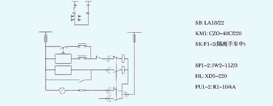
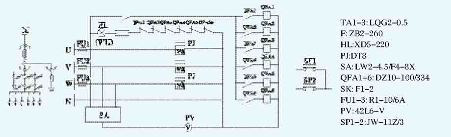
Circuit breaker control principle diagram

Isolation hand car between the corresponding circuit breaker hand car
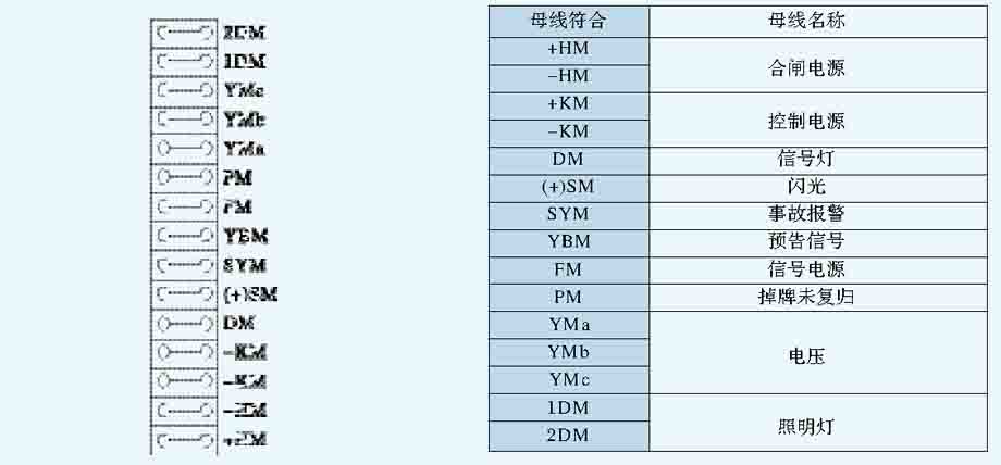
Control bus arrangement diagram
Pressure swing hand truck and the circuit breaker hand car
Switch cabinet base mounting hole
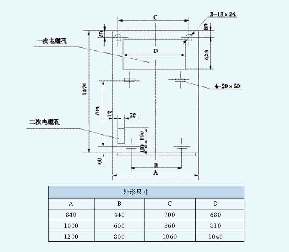
Foundation structure