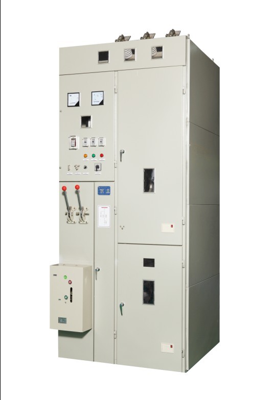
GG1A (F) -12kV fixed metal closed switch cabinet
- Brand:
- Type:

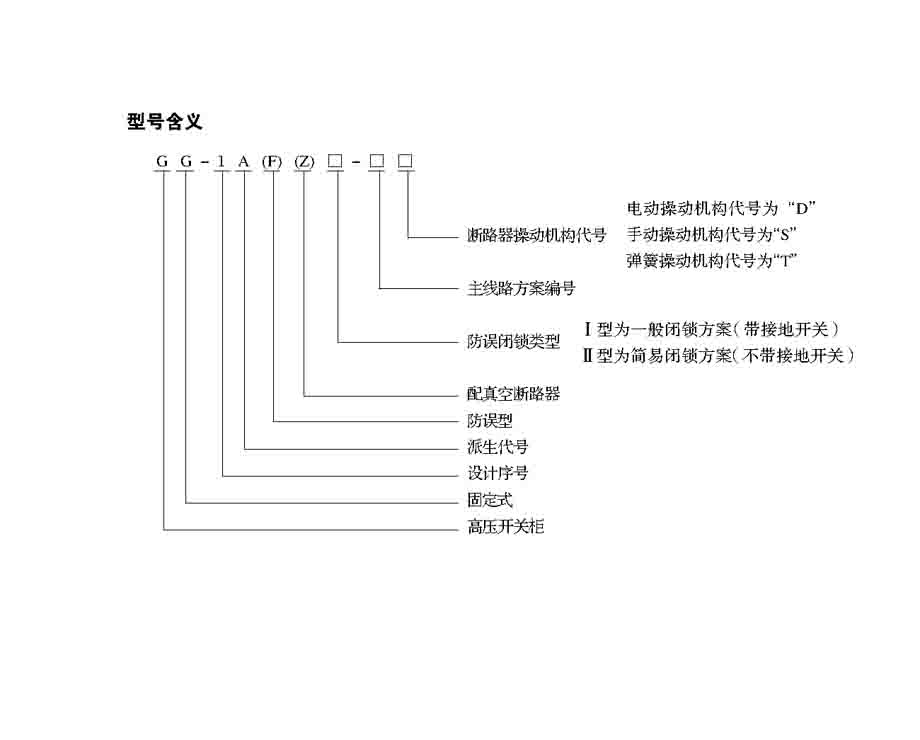
Model meaning
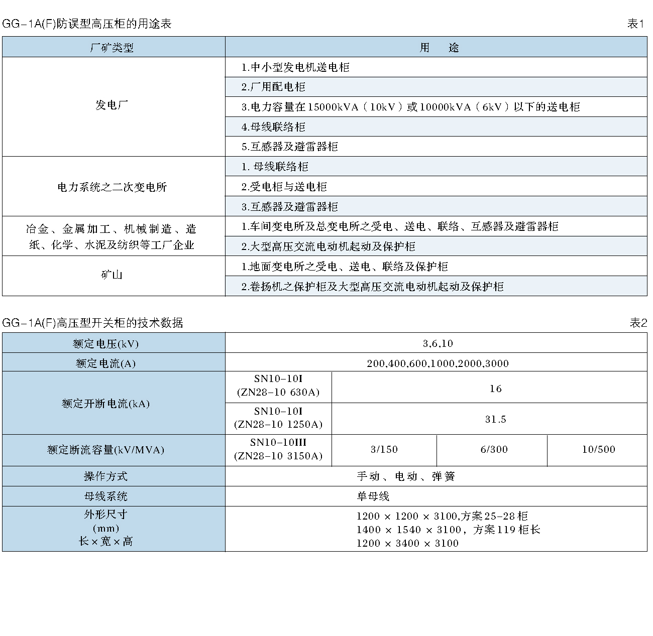
Technical data and program
GG-1A (F) (Z) type high voltage switch cabinet technical parameters see table 2;
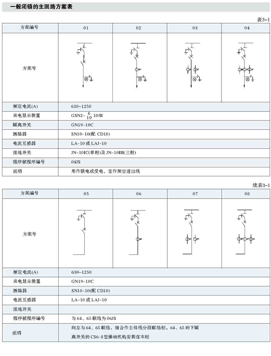
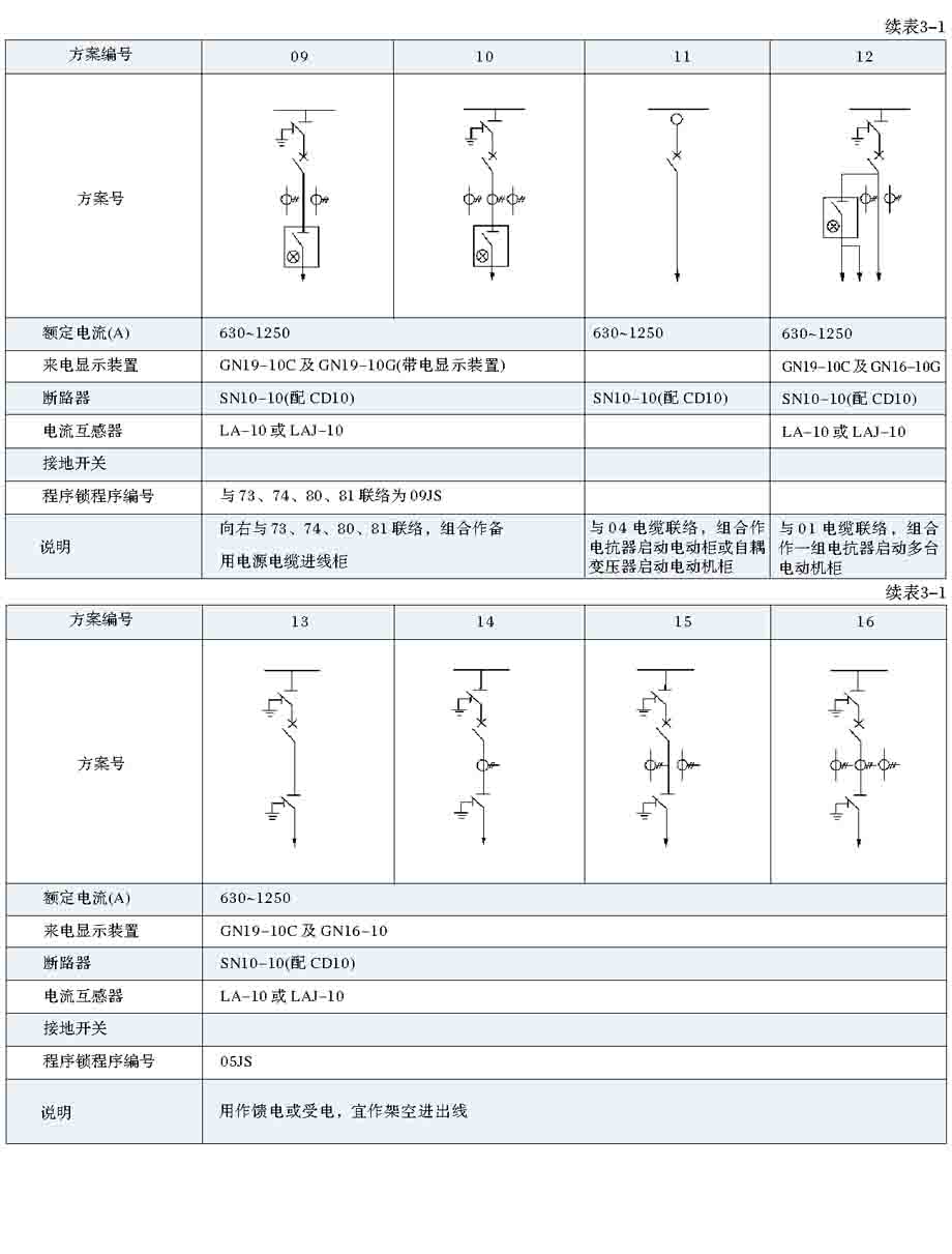
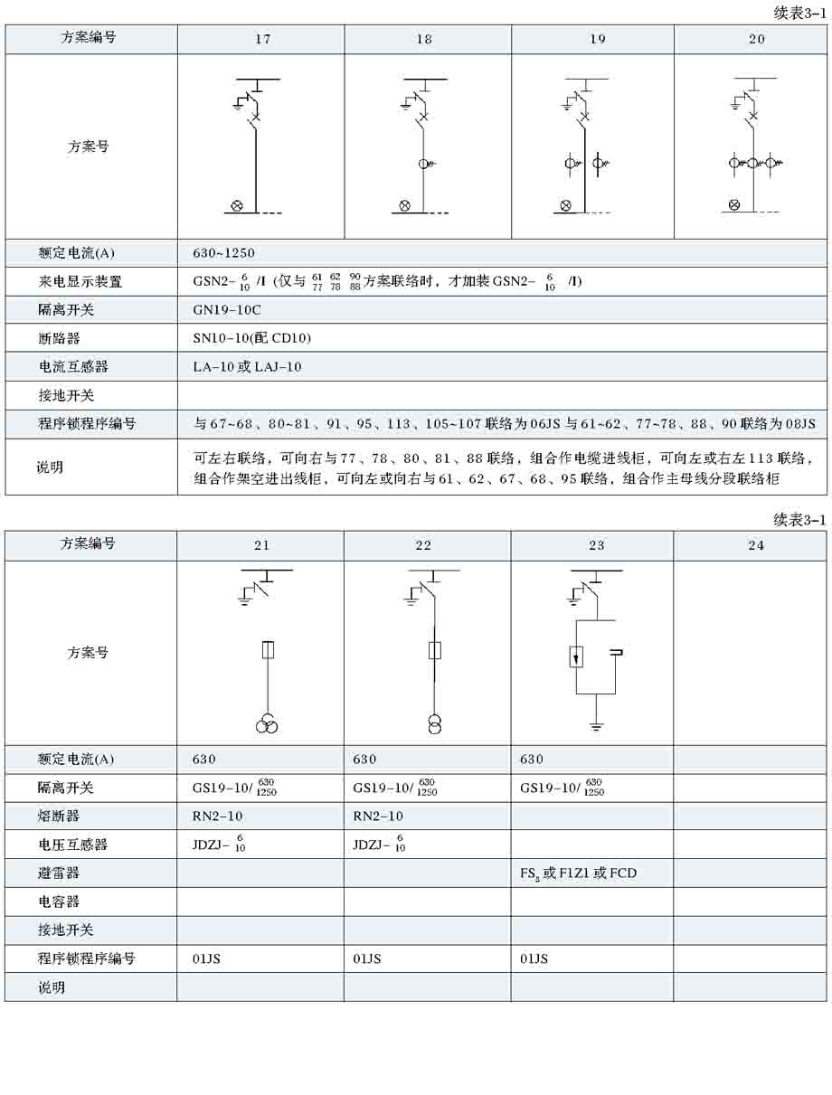
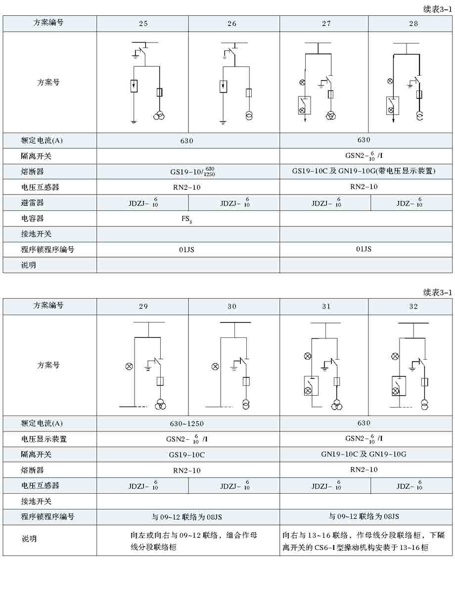
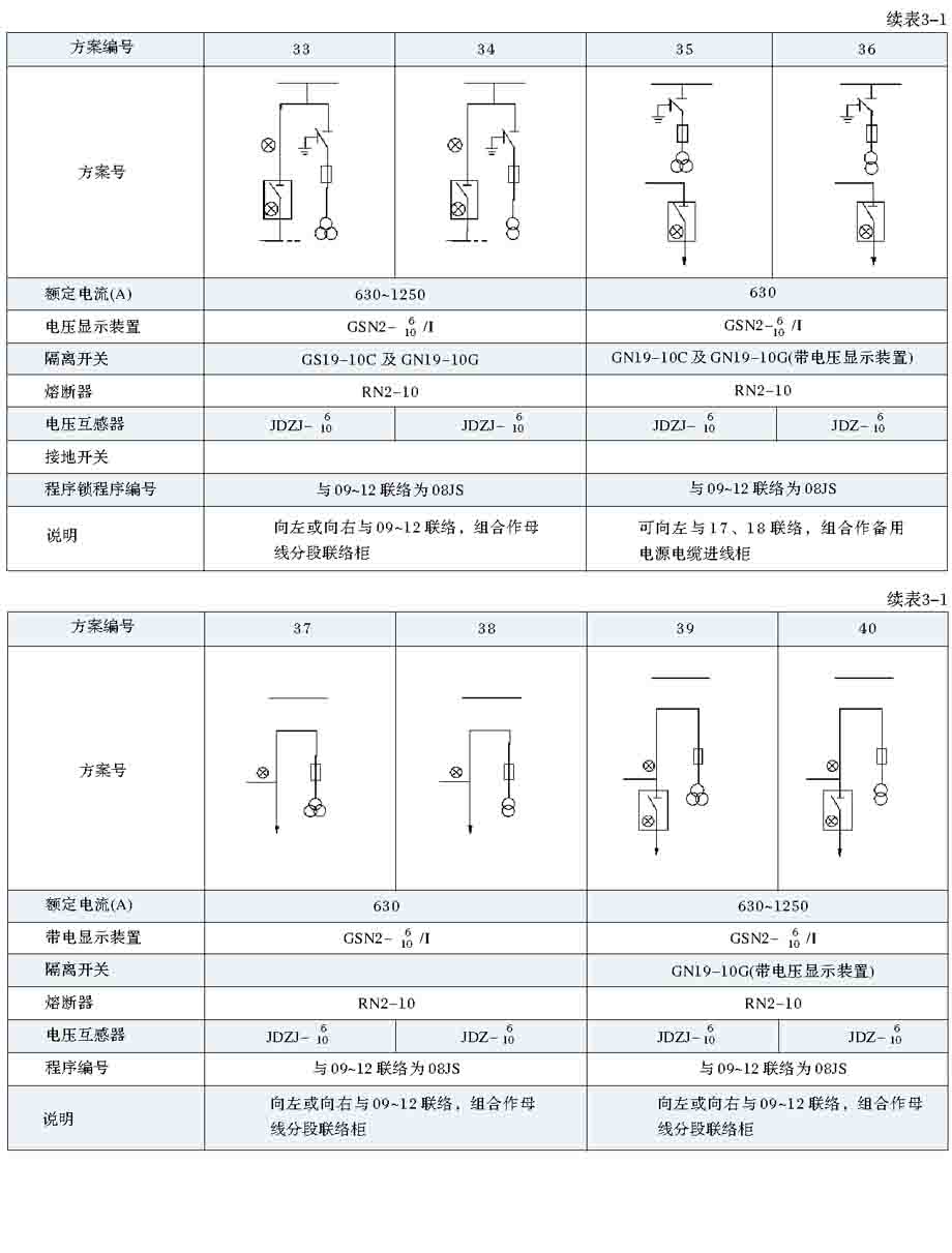
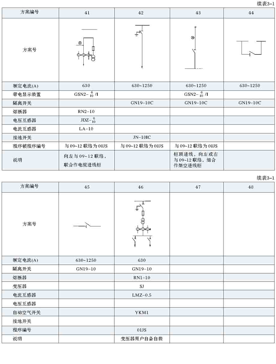
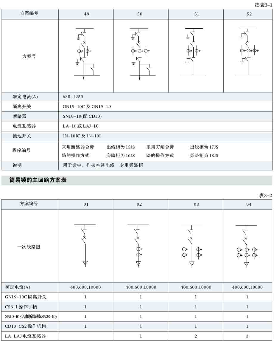
General locking the main loop scheme are shown in table 3-1. General atresia without considering 21-22,25-28,31-33 and the 37-39 main loop scheme, while not considering the circuit breaker equipped with CS2 type actuator scheme;
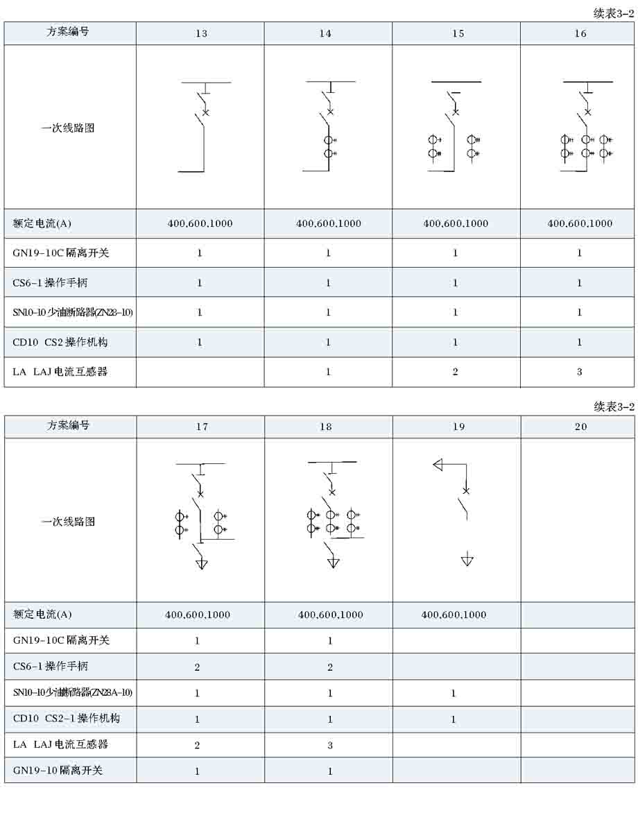
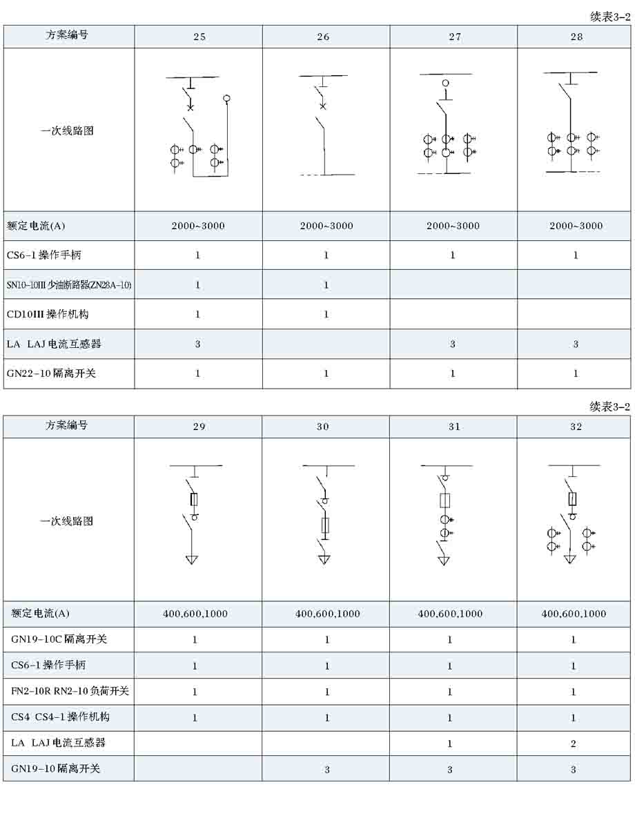
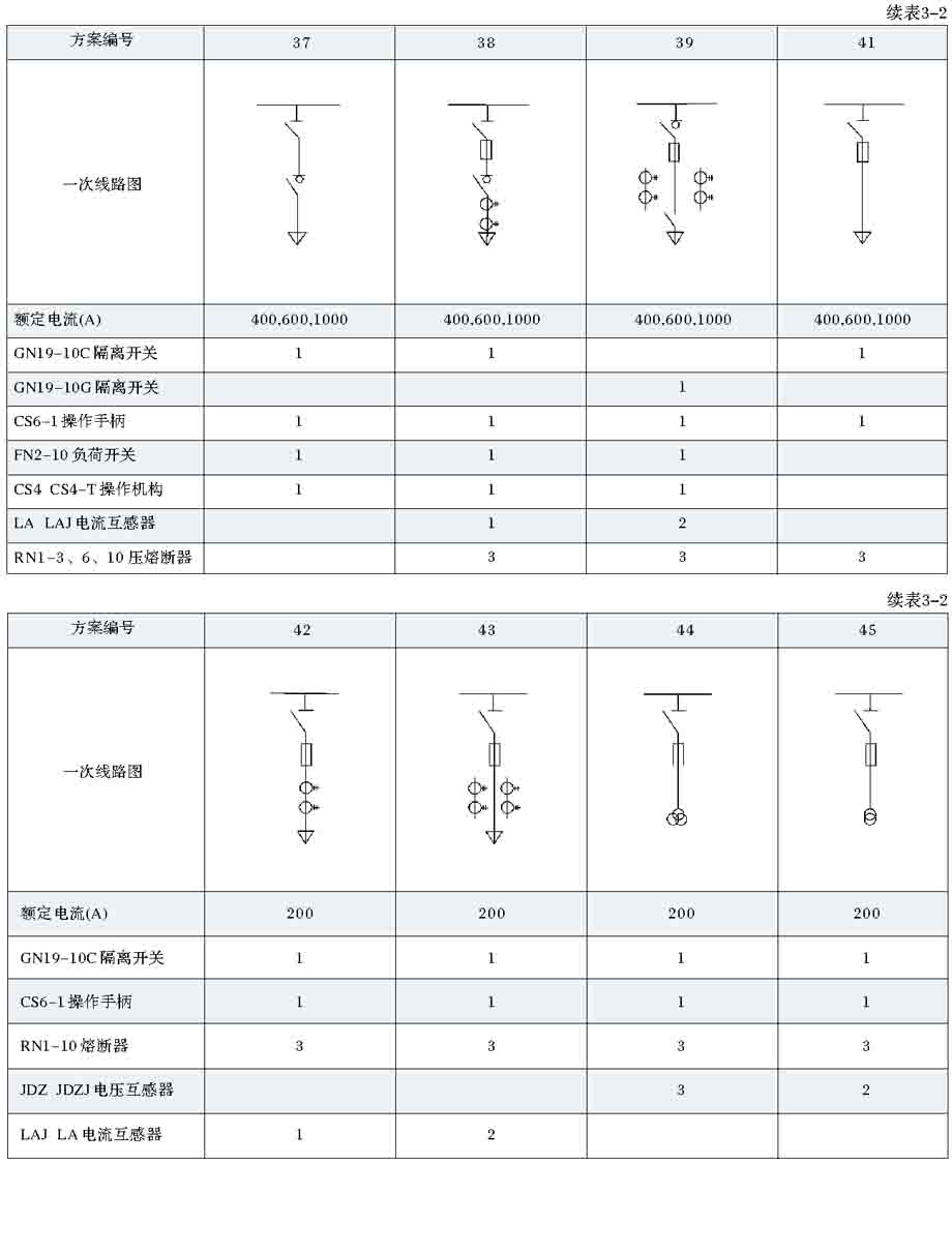
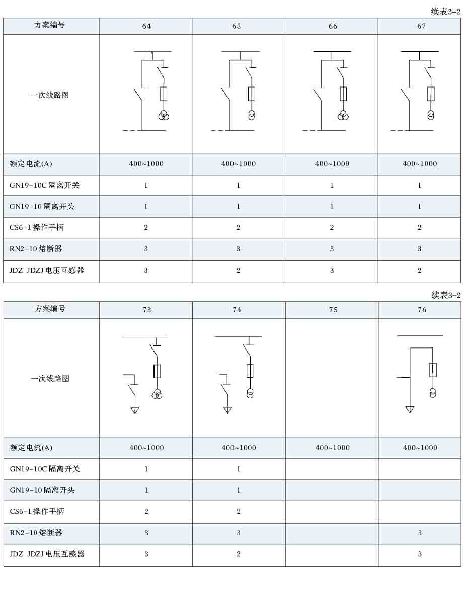
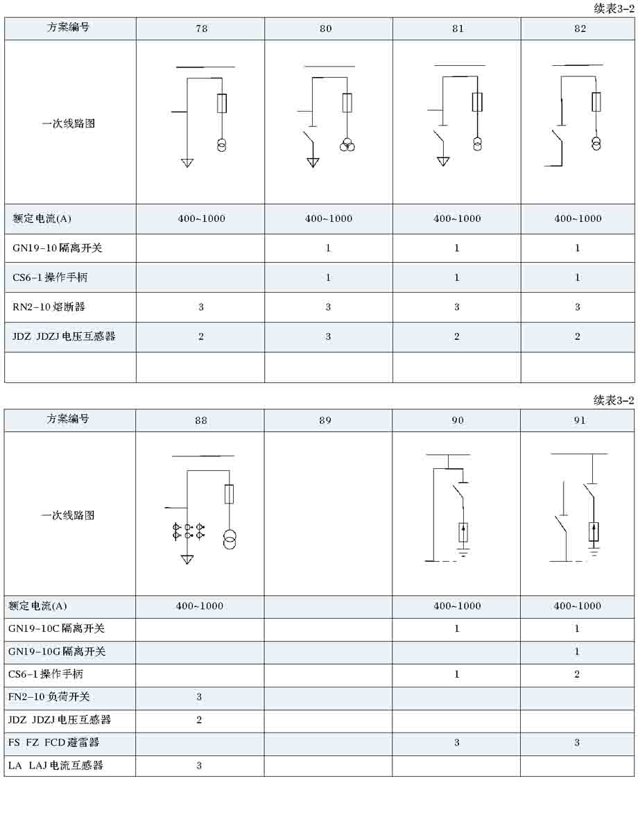
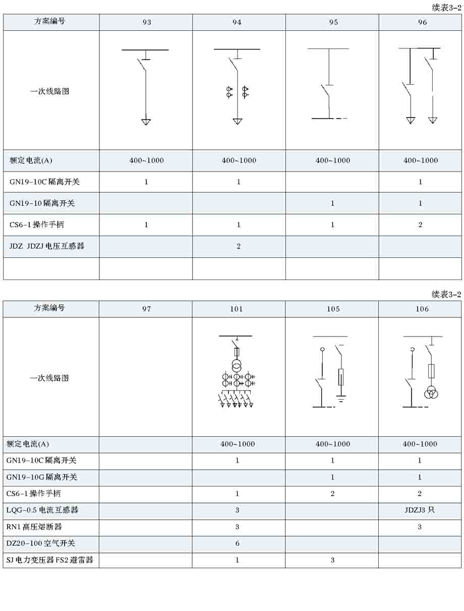
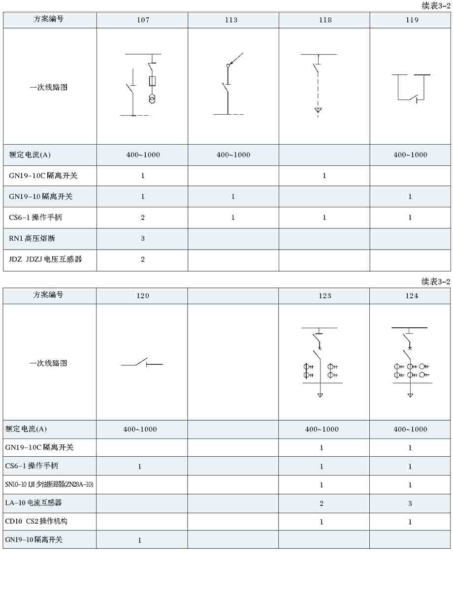
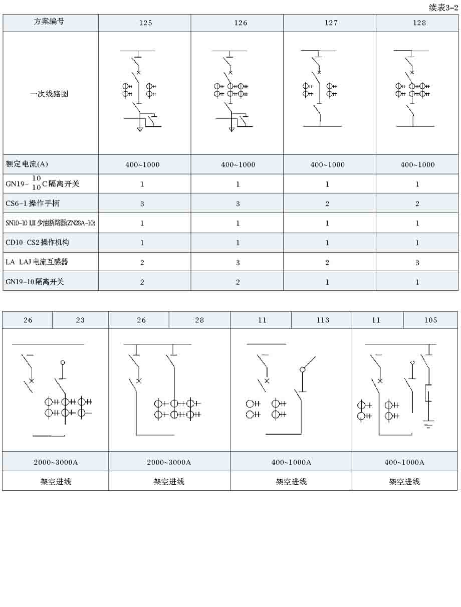
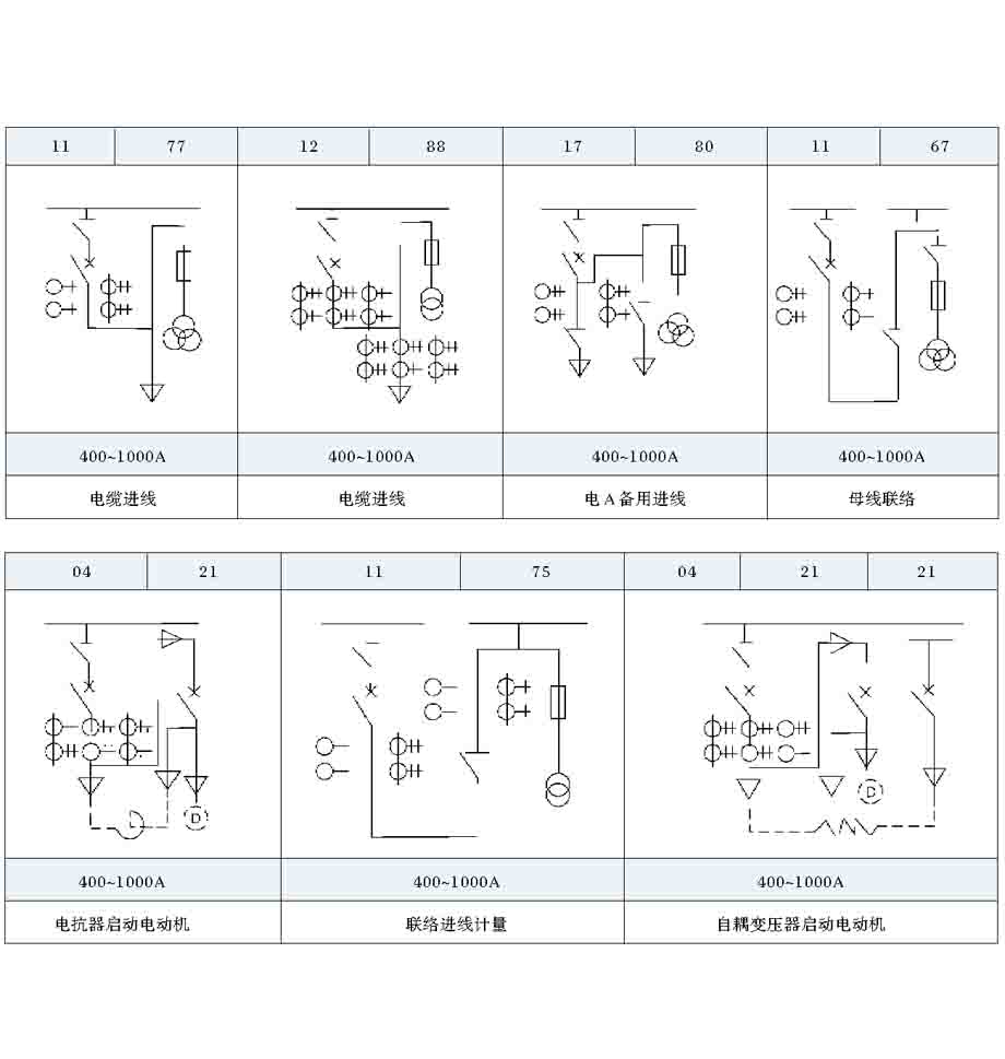
Simple locking of the main circuit scheme see table 3-2.
Use, maintenance instructions
1 closing (transmission):
A. close good door, the analog board "red green Command card" and operation cabinet corresponding change after insertion, closed isolating switch (program into the lock, also need corresponding JSN operation);
B rotation control switch or press the button to switch on the circuit breaker (such as the use of hand operating mechanism is closed circuit breaker);
C. will change the "red Command card" back into the simulator.
2 split gate (power off):
A. simulation in "red green Command card" and operation cabinet corresponding change after insertion, rotation switch or press the button control, circuit breaker gate (such as with a manual actuator when, opened circuit breaker).
B. pull the isolation switch (there are procedures for the lock, the need to operate the corresponding Cheng Xusuo);
C. will be replaced by the "Command card" inserted back to the analog board.
3 maintenance:
A. main bus or cable lines into electricity, maintenance of circuit breaker;
When the switch cabinet disconnect all, oil circuit breaker room to live parts are completely separated. And GG-1A (f) type I cabinet is provided with a fixed earthing switch, GG-1A (f) type II cabinet with a grounding pile end, so at both ends of the breaker can be grounded, so it can be safely into the circuit breaker room, circuit breaker, transformer, bus bar contacts parts of the maintenance.
B. main circuit without power failure, maintenance control circuit:
The cabinet of the relay room, terminal room in the structure has taken into account the safety of the inner part of the isolation, it can be carried out the assembly line operation.
4 all kinds of operations should be carried out according to the relevant regulations.
5 maintenance points:
5.1 bus and electrical contact points:
A. on a regular basis (about one year) to check the contact points, tighten the bolts to maintain contact pressure and re handle the high temperature contact point.
B. short circuit current is passed, to open all the contact check of welding phenomenon to re processing.
C. often keep the contact temperature does not exceed the following values: copper and copper contact: 90 degrees, aluminum and copper or aluminum contact: 70.
5.2 oil circuit breaker:
A. full capacity after breaking, in accordance with the instructions of circuit breaker overhaul.
B. apparent operating frequency of the current situation, the circuit breaker on a regular basis, static contact for inspection.
C. always pay attention to height, when the oil level is lower than the oil line to refuel.
5.3 load switch: off the two rated current or a short circuit over the amount of the switch, that is, to remove the arc room overhaul.
Two 5.4 circuit:
After the A. relay is fixed, it is not allowed to open the cover.
B. on a regular basis (about one year) tighten each contact screw, nut.
5.5 transmission part:
A. should always protect the flexible and accurate operation of the mechanical transmission system.
B. rotating part of the regular refueling.
C. regularly (about one year) check if there is abnormal phenomenon. The pin pin has been replaced and shear deformation).
5.6 procedures lock: do not often operate the switch cabinet, the program lock to be regular (about half a year) to operate a few times, so as not to rust.
5.5.7 maintenance of various electrical components shall comply with the respective installation and use requirements.
install
Waiting for installation products out of the box should be placed in a clean and dry room, installed with reference to figure 3 and Figure 11 manufacturing foundation. The installation steps are as follows:
The 1 switch is fixed on the basis of channel, available M12 anchor bolt welding can also be adopted.
2 switch cabinet with M12 bolt connection.
3. Install busbar: before installation should check the contact surface must be neat, clean and free of oxide film. Bus and cabinet all electrical contacts before put into operation are required to bolted close once again.
4. Installation of cable: cable fixed angle on the bottom of the cabinet, according to the corresponding rules terminated, the core wire connected to electrical outlet end. Cable number more than two should be added when distributing plate.
5. The installation of overhead wires, aluminum row from the upper part of the cabinet by parent support insulator and the outlet side isolation terminal connected, aluminum row and the other end of the wall bushing can be connected.
6. Cabinet grounding, the grounding wire is connected to the terminal of the indoor side at the lower part of the connecting wire screw or when the cabinet body is welded on the foundation channel steel, ground connection on the foundation channel steel.
7 according to the oil circuit breaker installed on circuit breaker oil and necessary debugging work instructions.
8 the drive system is accurate and accurate, and all the rotating parts should be coated with oil.
9 check the correct installation of the electrical installation of the entire two times to test.
Order notice
spare parts
When ordering, the two sides agreed to negotiate.
Order notice
1 the following information should be provided for the ordering party:
A. primary circuit scheme and arrangement system diagram;
B. distribution room layout;
C. two circuit diagram; (also according to the manufacturer's two line standard solution);
D. cabinets installed in a variety of electrical equipment, detailed specifications, quantity;
E. bus specifications can be supplied by the ordering party or by the manufacturer.
2 in addition to the above in order to provide complete ordering party, but also should be noted in the figure:
A. set high pressure cabinet is GG-1A (F) type ii;
B. outlet mode (overhead line or cable outlet);
C. is installed bypass bus.
If there is no description, according to GG-1A (F) type II cable outlet, the installation of the wall by the wall.
Program lock operation instructions
(for example, in the case of the 07D programme, the other scheme is a reference):
As shown in Figure: Program: GG-1A (F) I -07D.
Figure "." the key, "O" is no key.
1 power cut operation:
A. in accordance with the operation instructions, in the simulation to simulate the operation, take off the analog board 302 red signs.
B. to 302 switch cabinet, control switch on the handle of the red label, and analog board signs swap (for green), the operating handle switch, remove the center handle key. (if the sign is not interchangeable, control switch handle cannot operation, the center point of the key is not removed, then the next step will not be able to operate isolating switch).
C. insert the key lock in 3023 isolation switch operation, turned the key in the direction of the arrow, operating handle, pull the 3023 switch.
D. twist 3021 isolated hand holds the lock key, opened 3021 isolating switch, remove the key. (due to the effect of mechanical locking, only the first opened 3023, and then to open the 3021).
E. front door interlock mechanism due to the 3021 isolation has been lifted, the front door can be opened.
F. will insert the key into the back door (H) sent from the lock core, in the direction of the arrow key to open the door after the twist, the key is locked in the cabinet after.
G. will switch from the control switch to the plate into the analog board, so far, the power outage is completed.
2 the test of the oil circuit breaker during overhaul.
A. closes the door, take out the key. (the door is not closed, key out).
B. insert the key lock switch control center, for opening and closing test.
3 power transmission operation:
A. according to the instructions in the simulation board to simulate the operation, take down the 302 green signs.
B. to at the back door, shut the door took a key, if the key to the back door in the closing test in in the control switch is not removed, should be to control disposition of the switch gate after removal of the key).
C. to 302 before the door at the front door shut.
D. the back door out of the key into the 3021 isolation manual operation lock twisting, operation manual operating mechanism of the isolation switch, keys are atresia (if the front door is not closed, the isolation of 3021 not).
E. twist 3023 isolated hand lock key, the isolation closed, remove the key. (due to the role of mechanical locking, if the 3021 is not closed, then 3023 is also closed.
F. 302 control switch swap signs, turn red, and then insert the key operating handle on the center of the handle keyhole.
G. will replace the signs to the analog board to be red. So far, all the power to operate is completed.
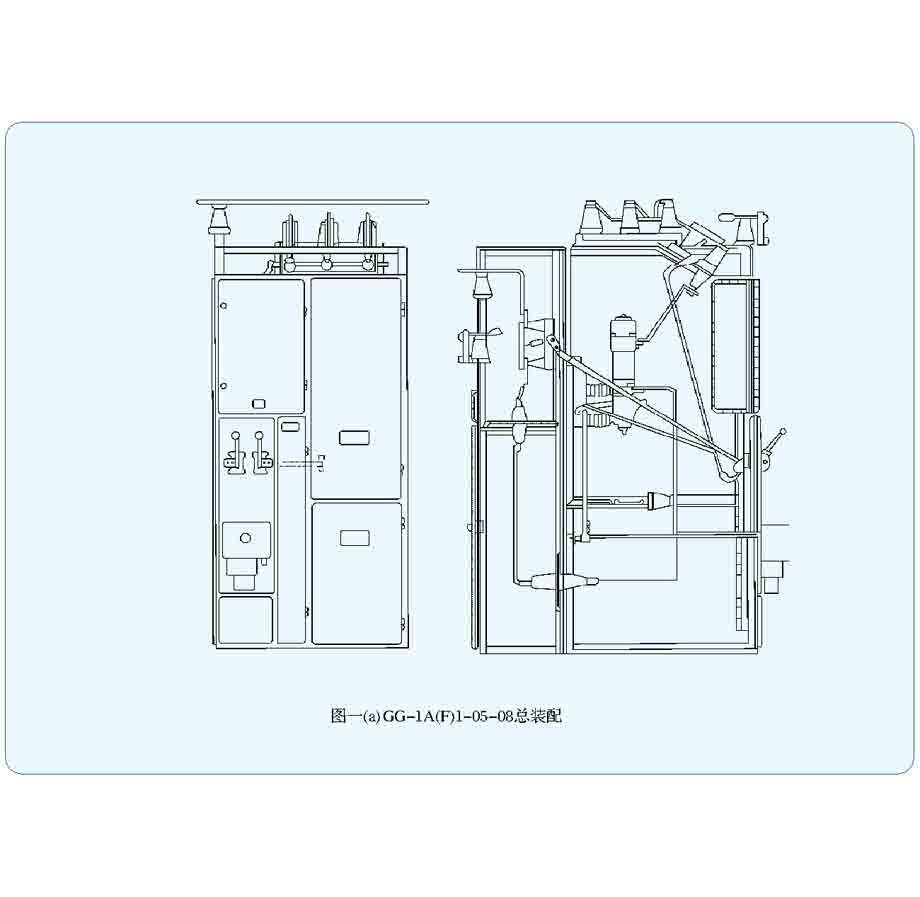
Total assembly of GG-1A (F) 1-05-08
Total assembly of GG-1A (F) 1-125-126 scheme
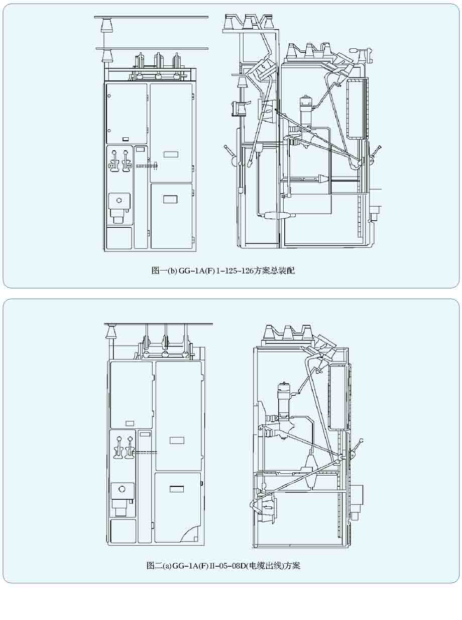
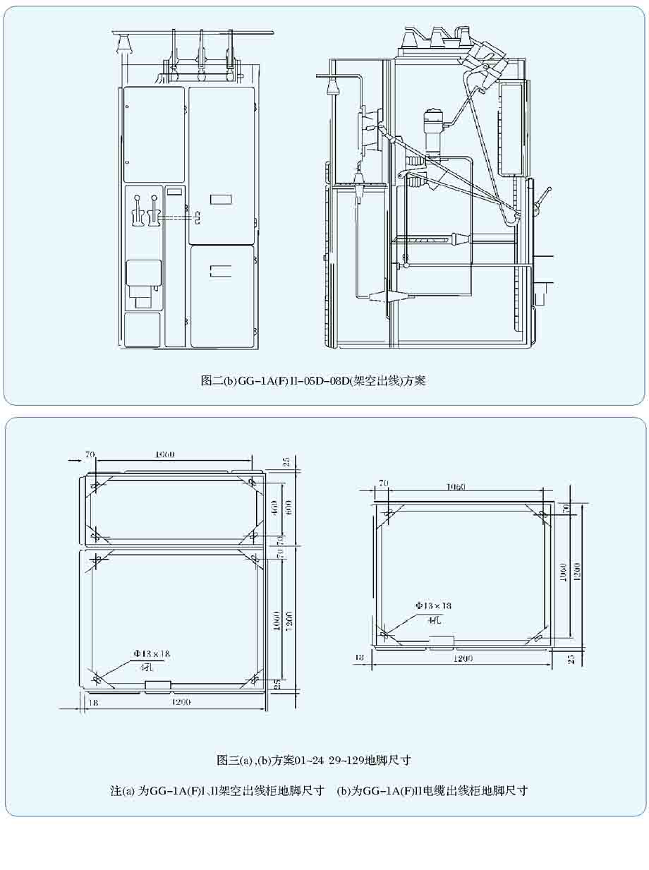
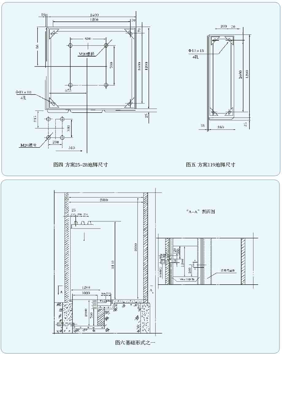
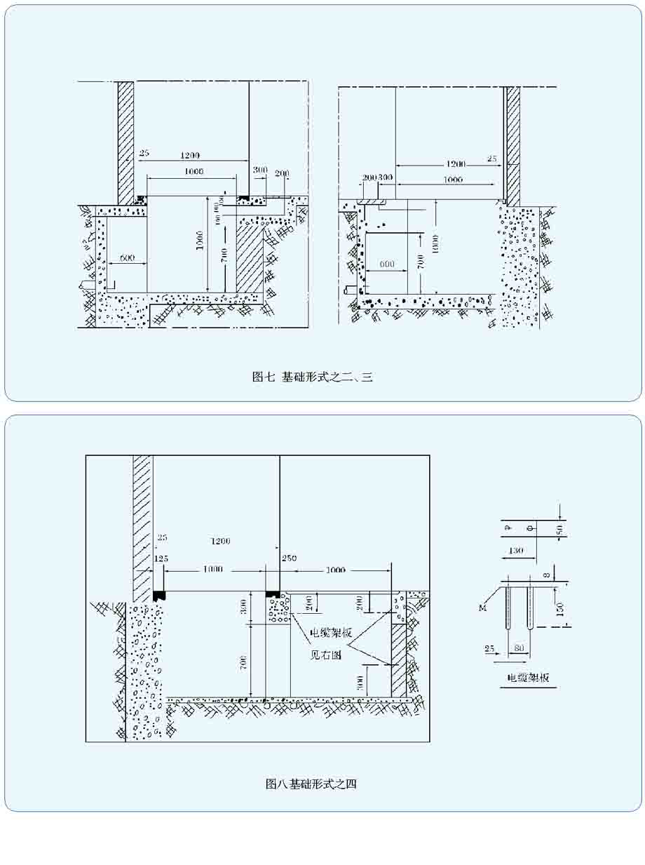
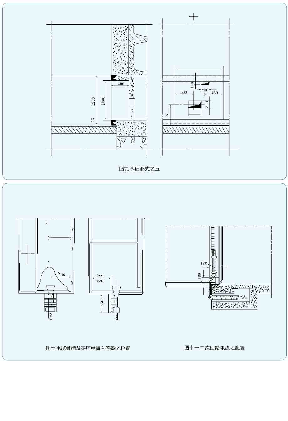
Table of main circuit scheme for general locking